Overview
The quality of gravity field results obtained from gravimetric inter-satellite ranging does not only depend on the ranging measurement accuracy. Equally important is the quality of the integration in the multi-sensor system consisting of inter-satellite ranging, GNSS orbit tracking, accelerometry, and attitude sensing, and the performance of this system as a whole. This applies already for the GRACE system but will be even more applicable for GRACE Follow-On (GRACE-FO). The accuracy of the GRACE-FO Laser Ranging Interferometer (LRI) is expected to substantially improve the gravity results but only to the extent that the primary length observable is not contaminated by systematic errors and noise from other components of the sensor system. The system performance is influenced, e.g., by star camera attitude performance, by the strength and characteristics of satellite pointing jitter coupling, by inaccurate knowledge and instabilities of phase centers and alignments, and by accelerometer signal disturbances. Several of these effects are related to influences from the platform and orbit environment.
The goal of the project is to identify improvements in sensor fusion, i.e., in combining the data streams of the multi-sensor system, with the perspective of extracting the best science signals. The project will establish and test a prototype system-level integrated observation model including several tasks: We will investigate the LRI observation model including all relevant physical and geometrical contributions. We will develop the analysis methods needed to extract improved pointing information from the LRI Differential Wavefront Sensing (DWS). We will investigate the combination of the two ranging systems – LRI and microwave K-Band Ranging (KBR) – to assess biases and noise, and to improve the accuracy of KBR data analysis. Finally, we will assess new methods to integrate the available sensor information on satellite attitude and pointing – including star cameras, gyroscopes, DWS, and dynamic attitude control data – which has proven one of the limiting factors in inter-satellite ranging.
The sensor fusion methods will be applicable in the GRACE-FO processing and may be adopted by the involved analysis centers. They will also provide valuable insight for inter-satellite ranging configurations beyond GRACE-FO.
Data Simulation
In cooperation with the GRACE-FO Mock Data Challenge (MDC) project (geo-Q B04), we have simulated a realistic set of GRACE-FO measurement data, for the purpose of testing and development of processing algorithms. In the following, the most relevant data for this project is listed.
Satellite Attitude
The satellites' attitudes are measured by the Star Camera Assemblies (SCA), consisting of 3 camera heads (one additional compared to GRACE) per spacecraft.
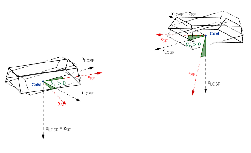
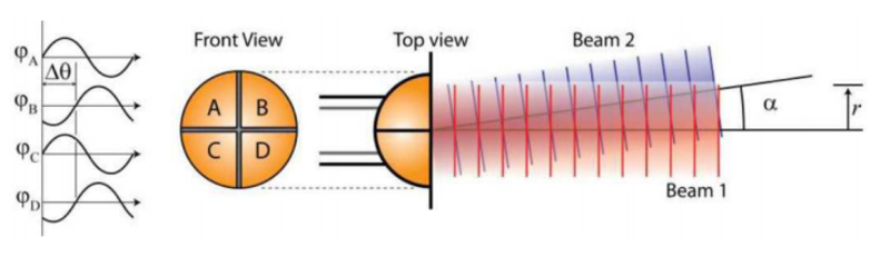
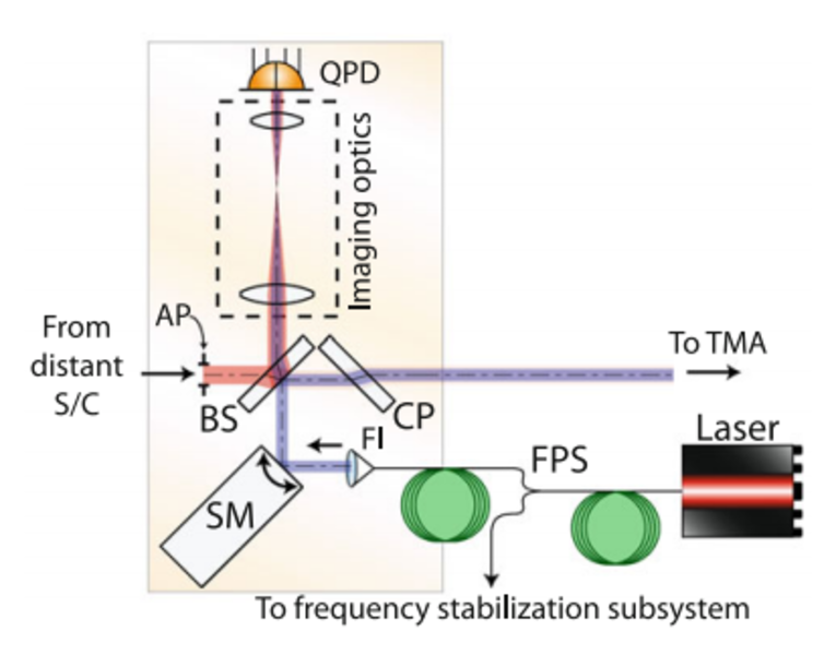
The LRI onboard the GRACE-FO satellites also measures the satellites' attitudes, which is necessary for the interferometer to function properly, since the laser beam has to be steered very precisely. However, it measures only pitch and yaw angles (as depicted in figure 01), using the Differential Wavefront Sensing (DWS) technique (figure 02).
We have created models of GRACE-FO pointing angles, by examining AOCS performance predictions provided to us by Airbus Defence and Space. These models allow us to generate an arbitrary amount of pointing data, the spectral properties of which are as realistic as we can predict, before the real data is available. We have studied SCA and DWS instrument noise sources, in order to test our processing algorithms with realistic measurement data. These simulations are also fed to the GRACE-FO MDC project (geo-Q B04).
Pointing Jitter Coupling (LRI)
Pointing jitter, i.e. deviations of the satellites' attitudes from their nominal attitudes, is causing non-negligible errors in the ranging measurement, both for the KBR and the LRI. It is expected to be the biggest noise source for the LRI, and it has proven to be one of the biggest noise sources for the KBR.
There are different pointing jitter coupling effects, some of which are expected to be negligible, but some of them not. It is also possible that there will be unknown effects. Therefore, a general description of pointing induced ranging error with linear (αi) and quadratic (βij) coupling factors might be valuable.
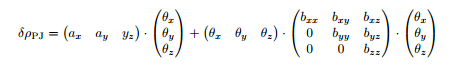
θx, θy and θz denote roll, pitch and yaw angles, respectively. There is one set of 9 coupling factors for each spacecraft - 18 in total - which can then be estimated during flight. Third order terms are not taken into account, since the pointing angles are already below milliradians, when the satellites are operating in science mode.

The interferometer laser beam is guided in a round-trip between the two GRACE-FO satellites, using the so-called Triple Mirror Assembly (TMA). It consists of three mirrors, which function as a retro-reflector, keeping incoming and outgoing beam anti-parallel. On each satellite, there is hence an imaginary point, the intersection point of the three mirror planes, called the Vertex Point (VP).
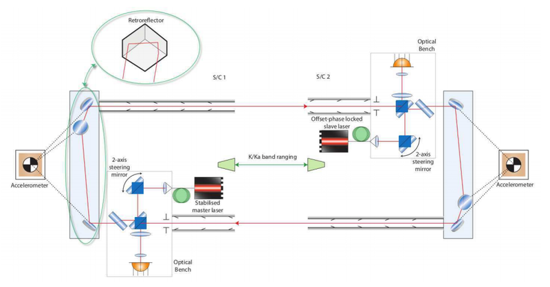
Due to the geometry of this setup, the LRI measures the distance between these two vertices. The points shall thus be placed directly in the pivot points of spacecraft rotation, i.e. the Centers of Mass (CoM). Imperfect assembling and large acceleration during launch impose, however, offsets between VP and CoM, leading to coupling of pointing jitter into the ranging measurement.

where P is the VP offset given in Satellite Frame (SF), and L is the line-of-sight vector, pointing towards the distant satellite. This formula shows the effect for one satellite; the effect then adds up for both. Further computations and a Taylor expansion yield the coupling factors for this effect, in terms of the VP-CoM offsets. We obtain linear coupling in pitch and yaw angles, besides second order coupling factors of different combinations. The offsets P are expected to be in the order of less than a millimeter in each dimension, but it is yet unknown.
Since the laser light has to propagate through at least one beam splitter (BS) on the optical bench, there is a change in the optical pathlength, which is also dependent on pointing angles. In fact, there is even a linear (first order in pitch and yaw angles) which is too large for the desired LRI accuracy. Hence, a so-called compensation plate is placed behind the BS on each spacecraft. It is another beam splitter of the same material, but rotated by 90 degrees w.r.t. the original BS. In the overall effect, this causes the linear terms to cancel out, but it doubles the quadratic ones. Computations based on the geometry of the LRI optical bench setup and based on optical properties of the beam splitter material show that we can expect contributions to the quadratic coupling factors βyy and βzz in the order of millimeters per square radians.
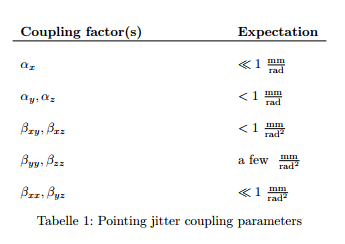
Note that the coupling factors are expected to be dominated by the TMA effect. However, based on our estimations, quadratic coupling factors βyy and βzz are of similar order of magnitude for TMA and BS errors. As mentioned above, there are other effects of pointing jitter coupling, which are not fully understood yet. The following table summarizes our pre-flight knowledge on the 9 coupling factors (same for both spacecraft).
Pointing Jitter Coupling (KBR)
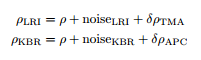
A geometric error, very similar to the error induced by the TMA-VP offset, is present in the KBR ranging measurement. It is also caused by an offset, here of the KBR antenna phase centers w.r.t. the CoM. In GRACE, this effect has been quantified using dedicated calibration maneuvers. This is also possible for GRACE-FO, and there is no reason not to make use of it. However, thanks to the redundancy due to the two ranging instruments operating at the same time, we predict that rough estimates are also possible to be derived from the normal data stream.
Other Noise Sources (LRI)
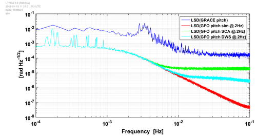
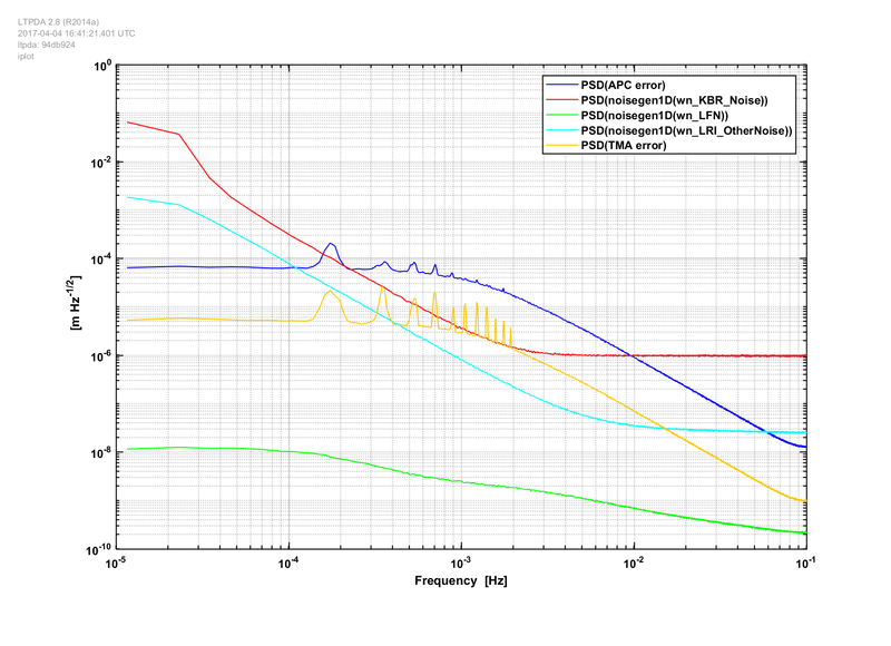
One well-studied noise source of the LRI is the laser frequency noise. We derived estimates of the resulting ranging noise, based on recent performance tests of the LRI cavities, which are already implemented in the satellites. The results show that the noise level of laser frequency jitter is much lower than in the mission requirements. This is very good news, since it is the only noise source which cannot possibly be tackled in post-processing, as the laser frequency carries the ranging information, i.e. it translates directly to the ranging signal. There are several other noise sources, to which a total noise budget of a few tens of nm per root Hertz (at high frequencies) has been allocated. The plot below shows the most important noise sources, exemplarily.
KBR instrument noise
The instrument noise of the KBR system has been studied in detail (Kim - Simulation Study of A Low-Low Satellite-to-Satellite Tracking Mission, PhD thesis, 2000). It is a large noise source and the limiting factor for the quality of the KBR ranging signal. It is due to different effects.
Estimation of Coupling Parameters
The pointing induced errors, as explained above, are dependent on unknown offsets. Before launch, one can only guess how large these offsets will be after the whole experimental setup has been subject to at least a few g of acceleration.
Proper combination of these measurements is the key for extracting the best ranging signal. First results confirm that coupling factors can be estimated with relatively low uncertainty, depending of course on the assumptions on offsets, length of the time series, and the estimation method. The development of algorithms for the estimation of these particular parameters is one of the goals of this project.
LRI Observation Model
For further, much more detailed studies on GRACE-FO data analysis techniques, it is essential to have a complete model of the LRI working flow. I.e., we must know what the final LRI ranging data stream which is sent to ground consists of, in order to retrieve the true ranging information ''hidden'' inside it. This is another goal of this project, geo-Q B02.
Principal Investigator
Callinstr. 38
30167 Hannover
Callinstr. 38
30167 Hannover


