The scope of the geo-Q project A01 is three-fold - each part focussing on a different topic of realizing a transportable absolute Quantum Gravimeter.
- I. In one part novel interferometry schemes are investigated to bring gravimerty with atomic ensembles beyond the state-of-the-art Mach-Zehnder-type Raman interferometers. Here novel techniques like Bragg interferometry, symmetric diffraction beam splitters and higher-order momentum transfer techniques are studied.
- II. Another part focusses on advancing the atom chip technology used for fast creation of Bose-Einstein condensates especially for the needs of ultra-compact absolute gravimeters. Here an atom chip teststand is realized and critical aspects like outgassing of the parts of an atom chip assembly, optical quality of the atom chip surface mirror and a simplification of the overall optical setup for robustification are investigated.
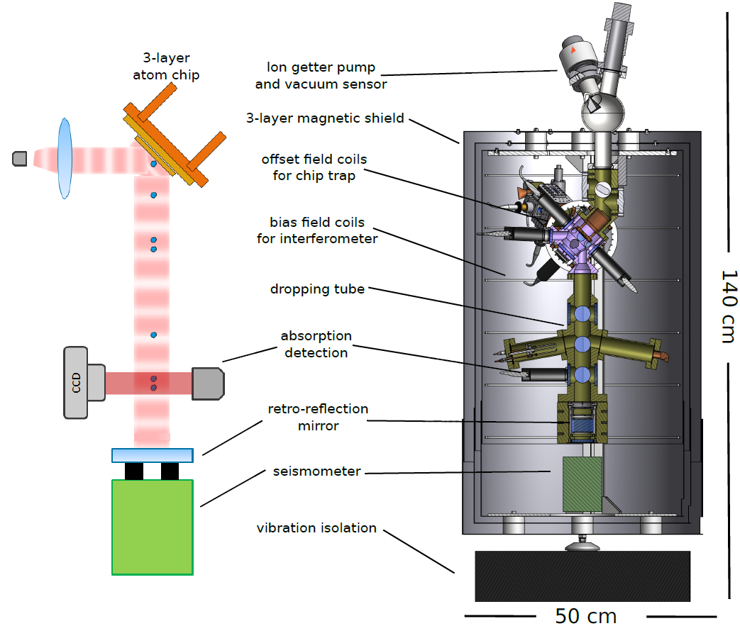
Figure 01: The experimental sequence is illustrated in comparison to the setup of the apparatus. The heart of the experiment is the three-layer atom chip, functioning as the atom trap and a mirror for the interferometry beam. The pulse sequence is applied during the freefall of the atomic sample in the dropping chamber. The seismometer indicated underneath the high-quality retro-reflection mirror can be used to compensate for vibrations.
- III. Finally an apparatus is under development, which will for the first time use Bose-Einstein condensates in a transportable setup for gravimetric measurement campaigns in relevant environments for geodesy. Besides being more compact and easier to operate than state-of-the-art cold atom gravimeters, this apparatus will additionally undercut the recent limits on accuracy of all gravimeters used worldwide.
The transportable quantum gravimeter will perform absolute gravimetry with quasi-continuous measurements beyond state-of-the-art performance by combining the advantages of current so-called classical absolute gravimeters (highly accurate gravity measurement) and continuously measuring devices (low drifts over long times and gravity measurement repeatability). It will thereby fill an important gap in the range of gravity sensors and thus enable monitoring oceanic, atmospheric and hydrological mass variations as well as solid Earth processes.
Compared to present transportable atom interferometers the quantum gravimeter combines for the first time a variety of innovations in a transportable device such as an atom-chip based source and novel interferometer types. Employing an atom source, which produces ultra-cold samples of atoms with temperatures below the µK regime or at quantum degeneracy, the transportable gravimeter can utilize atomic ensembles with very low divergence. This strongly reduces bias effects in the gravity measurement currently limiting interferometers based on laser-cooled atoms.
Introduction to the QG-1
Atom gravimeters based on Raman-interferometry with molasses cooled atoms (i.e. GAIN in Berlin or CAG-1 at SYRTE) are nowadays surpassing the performance of the typically used absolute gravimeters based on optically read out falling objects under vacuum (i.e. FG5-X). To make the next leap in absolute gravimetry, an apparatus based on Bragg-interferometry with Bose-Einstein condensates (BECs) is under development within this project A01 of the SFB geo-Q. Here, the fast BEC source [1] developed in the QUANTUS collaboration is adapted for a use in a transportable absolute quantum gravimeter setup. As depicted in figure 01 the three-layer atom chip assembly setup is positioned such, that the Bragg-interferometry beam is reflected of the chips mirror coating, pointing collinear to the gravitational acceleration and is then retro-reflected by an high quality reference mirror being placed inside the UHV-vessel and mechanically connected to an accelerometer. This setup will enable to operate a gravimeter based on Bragg-interferometry with BECs on a baseline of 320 mm with a repitition rate of >0.5 Hz. The use of BECs will mitigate mayor limitations in accuracy of cold atom gravimeters, especially due to wave-front aberrations of the interferometry light pulses and a residual coriolis contribution stemming from insufficient control of the starting properties of the molasses cooled ensembles.
[1] J. Rudolph et al. - ”A high-flux BEC source for mobile atom interferometers”, New J. Phys. 17, 065001 (2015)
Setup of the QG-1
In this section the overall setup of the transportable absolut Quantum Gravimeter QG-1, partitioned in the laser system, the control system and the sensor head, is described.
Laser system
The laser system of the QG-1 is based on an approach of using a fiber-based high-power laser amplifier at a wavelength of 1560 nm and subsequent frequency doubling [2]. A pigtailed DFB laser at 1560 nm is frequency doubled and stabilized via modulation transfer spectroscopy to an optical transition of Rubidium (see figure 02). This laser serves as a reference for a second pigtailed DFB-diode at 1560 nm, which is stabilized by a beat measurement to the reference light and amplified in a high-power amplifier with a total output power of 15 W. After frequency doubling, more than 2 watts of optical power at 780 nm are available in the free-space distribution module (see figure 03). Within this module the laser light is split into different paths for different functionalities necessary to operate the double-MOT-system, the interferometer and the detection.
The whole laser system is setup up to fit into the temperature stabilized transportable rack.
[2] O. Carraz et al. - "Compact and robust laser system for onboard atom interferometry", Applied Physics B, October 2009, 97:405
Control system
The control system is based on LabView by National Instruments. This software is used to program the experimental sequence, an automatic optimisation routine based on a genetic algorithm and for housekeeping. To guarantee a precise timing, a FPGA is used to control all other electronics of the system. The compact electronics to control e.g. the lasers or the atom chip assembly are based on the developments within the QUANTUS collaboration. The whole control system fits into the temperature stabilized transportable rack and is fully remote controllable.
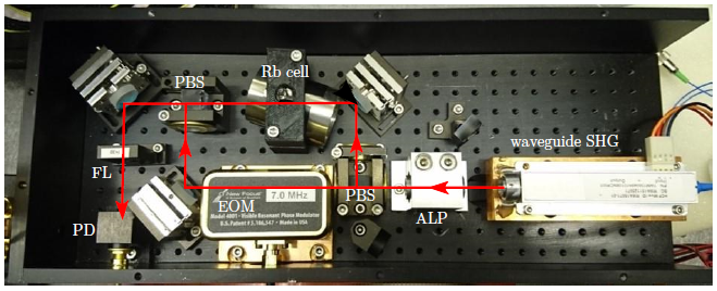
Figure 02: Reference module: The laser light enters the module through a waveguide second harmonic generation. It is passing a focal lens pair (ALP) before it is split into pump and probe beam. The pump beam is frequency modulated with an EOM. Probe and pump beam are overlapped in a rubidium gas cell. The probe beam is focused by a lens (FL) with a focal length of 30mm before the signal is detected with a fast photodiode (PD). The empty mirror holder underneath the first PBS is blocking the passing pump beam while the mirror above the ALP guides the reflected beam from the glass cell onto the wall for laser safety.
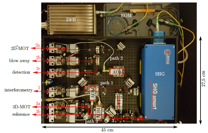
Figure 03: The distribution module: After generating laser light in the 1560nm regime (DFB), frequency sidebands can be imprinted on it by using an EOM. After frequency doubling (SHG), the 780nm light is split into three main paths by polarizing beam splitters. All paths can be switched on and off by using the first diffraction orders of the AOMs for the beam alignment. Bistable shutters for each fiber coupling unit provide additional switching possibilities. The beam transmitted through both PBSs (path 3) is used for the cooling light in the 3D-MOT and as a reference or diagnostics port. The light reflected on the first beam splitter (path 1) is doublepassing an AOM and coupled to collimation optics for the interferometry beam. Path 2 addresses the fiber splitter for the 2D+-MOT, the detection collimator and the blow away beam applied before the interferometric sequence.
Sensor Head
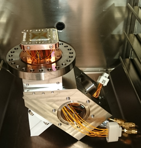
The heart of the sensor head resembles the high-flux BEC source. Here a double-MOT-system is combined with a three-layer atom chip setup (see figure 04) to generate BECs of up to 4x10⁵ Rubidium atoms within 1.6s [3]. To guarantee an ostuction-free propagation of the interferometry light, the atom chip assembly was slightly altered in a way, that the high-reflection coating of the atom chip serves as reflector for the interferometry light to re-direct its propagation parallel to the gravitational acceleration. After propagation through the drop tube, which features several viewports for future more advanced interferometry schemes, the interferometry beam is retro-reflected by a high-quality in vacuum mirror, which is placed inside a tip-tilt frame to compensate for the coriolis effect.
A titanium sublimation pump, as well as passive getters and IGPs are used to maintain an UHV environment inside the vacuum chambers, which are solely fabricated out of titanium. A cylindrical three-layer mu-metal shield prevents magnetic stray fields to enter the interferometry region. The whole sensor head is placed onto a vibration isolation stage to passively reduce environmental vibrational noise.
[3] J. Rudolph et al. - ”A high-flux BEC source for mobile atom interferometers”, New J. Phys. 17, 065001 (2015)
BEC source system of the QG-1
The BEC source system consists of a double-MOT setup combined with an atom chip assembly. Up to date the functionality of this system could be proven by the demonstration of a 2D- and 3D-MOT. Recent activities concentrate on optimising the 2D-MOT performance to increase the loading rate into the 3D-MOT in the next step.
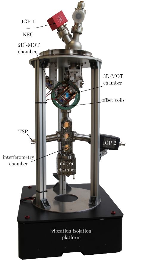
Figure 05: Sensor head setup on a passive vibration isolation (without the magnetic shielding): The top of the experimental chamber is composed of an ion getter pump (IGP) combined with a passive getter (NEG), a pressure sensor and a valve. A platform supported by three rods builds the basic structure for the Mu-metal shield. Underneath the platform the 2D-MOT chamber, the 3D-MOT chamber, the interferometry chamber and the mirror chamber are presented. Left of the interferometry chamber the titan sublimation pump (TSP) is mounted opposite to a second IGP compensating for high outgasing rates at the beginning of the pump process. The whole apparatus is placed on a passive vibration isolation platform.
Principal Investigators
Schneiderberg 50
30167 Hannover
Welfengarten 1
30167 Hannover
Welfengarten 1
30167 Hannover


